
No process operates with 100% efficiency. In other words, while some energy is converted into useful output, a portion is always lost as heat. This heat must be removed from the device to prevent overheating. Therefore, thermal management must be considered in all designs. Heat naturally propagates from the hotter to the cooler areas, so in many cases, we can rely on nature to manage it. Heat is transported through several mechanisms: radiation, convection, and conduction, are the primary physical processes involved. Additionally, phase transitions and the Peltier effect are also important to consider.
Radiation, convection, and conduction will occur spontaneously, and if equilibrium between heat input and heat removal is achieved at an acceptable temperature, no additional engineering is required. However, if the equilibrium temperature is too high, heat removal must be enhanced through deliberate thermal management strategies. To achieve this, all the heat transport mechanisms can be utilized.
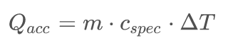
Just a note on therms, the topic of keeping electronics cool is also called heat management or electronics cooling. The end goal is to keep the temperature of the components in a range where they will function correctly. That is done by managing the heat energy (Q) with unit J. The rate of change in the energy is Q̇, time derivative of the energy with unit W. Temperature change ΔT and energy accumulated (Q_acc) in a substance are related through the specific heat capacity (c_spec).
 (1)
(1)
where,
m is the mass,
c_spec is the specific heat capacity and
ΔT = change in temperature
It agrees with our intuition. The heat result in a temperature increase.
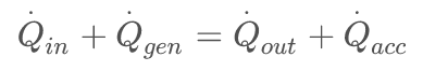
If we look at the rate of changes in heat Q dot (Q̇) we can write the rate balance or power balance.
 (2)
(2)
where:
Q̇_in is the input heat rate [W]
Q̇_gen is the generated heat rate [W]
Q̇_out is the extracted heat rate [W]
Q̇_acc is the accumulated rate [W]
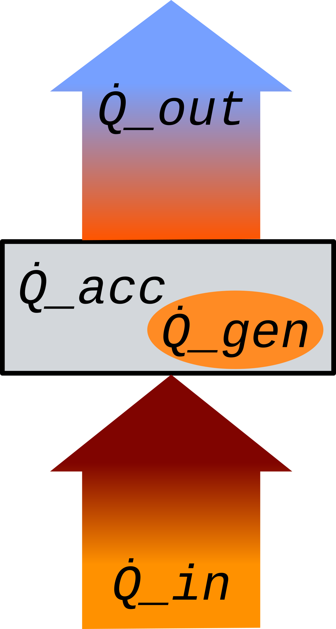
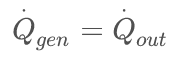
As it can be seen, we can only allow a certain heat accumulation (Q̇_acc) to keep the temperature increase bound to safe limits. The aim with heat management is to make sure that the system reach equilibrium where Q̇_in + Q̇_gen = Q̇_out and Q̇_acc = 0 W. This has to happen at an integrated Q̇_acc = Q_acc corresponding to a safe temperature increase.
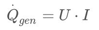
In electrical circuits we have a heat generation from voltage drop (U) associated with a current (I), so.
 (3)
(3)
We have to design a cooling system with heatsinking so that below the maximum allowed temperature (T_max) we have power equilibrium.
 (4)
(4)
This is reach through some activities described below.
Heat management awareness
Heat management awareness throughout a design process is the most important and often missed. It must be a failure in courses. It is assumed that if students pass their first semester Thermodynamics course, then they are automatically heat management aware when placing components on a PCB 6 years later. There are some more reasons why heat management is missed. The individual subsystem seen in isolation does not give any overheating problems. A PCB tested alone on a test bench might not heat much. Heat flows from the hot to the cooler. So the passive dissipation solves the problem. When the PCB is integrated in an enclosure together with other subsystems, with their own heat dissipation and less convection, that is when the issue shows. A PCB in a rack or box is a complicated thermodynamic system and the factors that impact the heat management goes across several subtasks, circuit design, parts selection, layout, and mechanical design. Heat management awareness has to be present in every step of the product development, assembly, installation, and use.
Put a laptop on a duvet, and the heat management simulations are to no avail. Assemble a heat sink with metal burr or flux residue on the contact surface, and the conduction is a small fraction of what the specifications say they should be.
A small anecdote; In a system a high power laser diode was connected to its laser driver with a length of solid wire. A design improvement allowed the laser diode to be soldered directly to the laser driver. The result was overheating of the laser diode and of the driver. No one had thought about the heat aspect of two 25cm long solid wires, that actually provided the necessary dissipation. Another story from fiber optics. Filter pump signal combiner or WDM have quite low loss 0.5dB the heating from a 400mW pump is not much, ~20mW. They are fragile components shipped in polystyrene foam boxes. I saw the result when someone powered it inside the shipping foam, adiabatic heating; Q̇_out=0W, it gets really hot.
It helps if everyone involved think about heat generated and where it ultimately goes. There is no final resting place for the heat, but it can be dissipated in a heat sink. We call a metal block with fins a heat sink, but it is a bit of a misnomer, it is a heat dissipater. A heat sink is a mass of substance, so large that the input heat does not change its temperate. Basically it needs to have infinite mass. The earth's atmosphere is a heat sink for the level of power and time spans we create, the ocean too is a good heat sink. I like to bring that up because I have worked in a laser lab with two laser chillers. It is nice and warm in the winter, but during summer it only works with the windows open. Hanging the heat exchanger on the outside wall ends up cheaper than handing out laser goggles to everyone on campus.
Analytical models
I will paste some formulas in here, for the case that you recycled your textbooks. There are many treatments of the topic out there. I will summarize just enough for doing some rough calculations. The analysis is based on the energy conservation expressed as the rate balance for an imagined control volume, eq. 2.
The in- and out- terms can have contributions from heat conduction, convection and radiation.
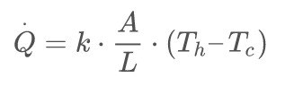
The law of heat conduction, also known as Fourier's law, states that the rate of heat transfer through a material is proportional to the temperature gradient and to the area, through which the heat flows.
 (5)
(5)
where:
Q̇ is the time derivative of the amount of heat flowing through a cross-section of the material,
A is the cross-sectional surface area,
(Th – Tc) is the temperature difference between the hot and cold ends,
L is the distance between the ends,
k is the material's conductivity, [W·m−1·K−1]. See Thermal Conductivity of selected materials below in the Interface materials section.
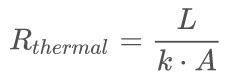
The dimensions A, L and k the conductivity constants are sometimes joined in one thermal resistance constant.
 (6)
(6)
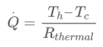
Using the thermal resistance the heat conduction can be written.
 (7)
(7)
Often the thermal resistance in kelvin per watt (K/W) is listed in datasheets.
It is fairly easy to identify the heat conduction paths and estimate the heat flow.
One of the other three main heat transfer mechanisms is convection.
Convective heat transfer, Newton's law of cooling frequently referred to simply as convection, is the transfer of heat from one body to another by the movement of fluids.
Newton's law of cooling states that the rate of heat loss of a body is directly proportional to the difference in the temperatures between the body and its surroundings.
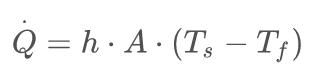 (8)
(8)
where:
T_s is the surface temperature [K],
T_f is the temperature of the surrounding flow medium [K],
Q̇ is the rate of heat transfer out of the body [W],
h is the heat transfer coefficient (assumed independent of T and averaged over the surface) [ W/m2*K], example Air (natural convection) h is in the range 5-25 W/m2*K. Often used approximations for PCB’s are, natural convection 10 W/m2*K and forced convection 50 W/m2*K,
A is the heat transfer surface area [m2].
The equation is simple enough to for making some calculations and gives an estimate. It is most accurate for passive convection without cooling fans. With forced flow the temperature will always be lower. The equation gives an upper limit.
Some important observations, a larger area A gives more heat removal by convection. If the parts are designed to operate at some elevated temperature then they can dissipate more heat. If we look at a PCB with a thermal camera and see some components at elevated temperature it can be a solution rather than a problem, given that the component is designed for it. One has to observe the maximum value of T_f.
If the system has to be specified for a surrounding temperature of 75°C then a ΔT of 30°C might bring the component out of its operating range.
The third basic heat transfer mechanism is radiation. The thermal radiation law ( Planck's law) describes the electromagnetic radiation power emitted by a black body in thermal equilibrium at a given temperature T_h. An incandescent bulb is build to minimize the heat conduction and convection, so radiation become the dominant mechanism of heat loss. The filament reach a temperature of over 2000°C where the thermal equilibrium is reached and dissipated heat is removed by radiation.
The total power emitted per unit area at the surface of a black body (Q̇) may be found by integrating the black body spectral flux found from Lambert's law over all frequencies, and over the solid angles corresponding to a hemisphere above the surface.
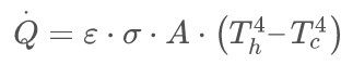 (9)
(9)
where:
ε is the emissivity < 1, =1 for black body,
σ = 5.6704E-8 Js-1m-2K-4, Stefan–Boltzmann constant,
 (10)
(10)
A is the surface area [m2].
T_h is the temperate of the hot surface [K],
T_c is the temperature of the cold surroundings [K].
The radiated heat follow a temperature to the power of 4 relationship. This agrees with our experience that radiation really kick in at high temperatures. Still there is significant thermal radiation at room temperature. A thermal camera works by detecting the thermal radiation and estimating T_h. We can understand from the formula that the thermal camera images has to be compensated for the emissivity of different surfaces, and it has to be calibrated for T_c.
Numerical models
The analytical models can be to estimate the equilibrium temperature of devices and adjustments to the heat transport of the system can be adjusted, so the temperature is safe.
The equations are simple and can be solved on paper or using spreadsheet, or programming language, python, Mathcad, etc.. They are the integrated form of the differential equations that include the variations in space. If you are researching a new aspect of the heat management or developing models you will have to code the differential equations and use numerical resolution.
There are several software packages for thermal simulation, e.g. Solidworks Thermal stress analysis module, SimScale, Simulaton and more.
Using numerical models does not shortcut the analysis. It is important to first make an analysis for the problem. It takes time to define the actual physical parts of the real system and the finite element analysis may require a fine mask to resolve features, this give a long computation time. Basically you have to simplify the system with a good understanding of where the heat is flowing. The analysis is a forward estimation of what the temperature will reach in a given physical design. The designer has to iterate the design until the output is an acceptable temperature.
Experiments
Real measured data is the most convincing. Make sure that the test setup is representing the live system correctly. Also use observation time for each test case which is long enough to reach steady state. Often electronics boards have temperature sensors as part of the design, make sure to use those. Flow and temperature sensors will always give a perturbation to the system. Using onboard sensors allow a comparison with and without added sensors. Thermal cameras offer low intrusion measurement, but they measure the thermal radiation not the temperature. The emissivity ( epsilon ) vary a lot between a black IC and metal. Thermal printer paper can be used to locate a hotspot on a PCB. Press the paper against the PCB for some seconds with a foam sponge. The hot parts will give a color change. There are Heat-Sensitive Papers with different temperature thresholds.
If the system used forced airflow with fans, then make sure that your setup allow variation of the fan speed, usually just reducing the voltage. High fan speed gives noise and vibration and wear down the fans quicker than lower speed. Find the lowest acceptable speed and verify that the temperature has the expected dependency on flow speed. If it does not, then maybe the flow path is not as intended.
Heat management add-on’s
If the passive cooling in insufficient then we can add fans, heat sinks or even liquid cooling. These are design element with the main purpose to increase heat conduction and convection.
If passive dissipation from a PCB is not enough to keep the component temperature within safe limits then we start adding features designed with the purpose of increasing heat dissipation. Here we go over features that can be added to a design to prevent overheating.
Starting with the lowest cost features we have the extended pads. Copper is a good heat conductor, so copper area on the PCB can be used to spread the heat to larger area for dissipation. High power components often have packages with an exposed pad or flap made for heat conduction interfacing. Designing a footprint with a pad that expends around the components give an exposed copper area from which heat can escape via convection. Vias can also be placed under the component to conduct heat to the PCB bottom layer to increase the dissipation area.
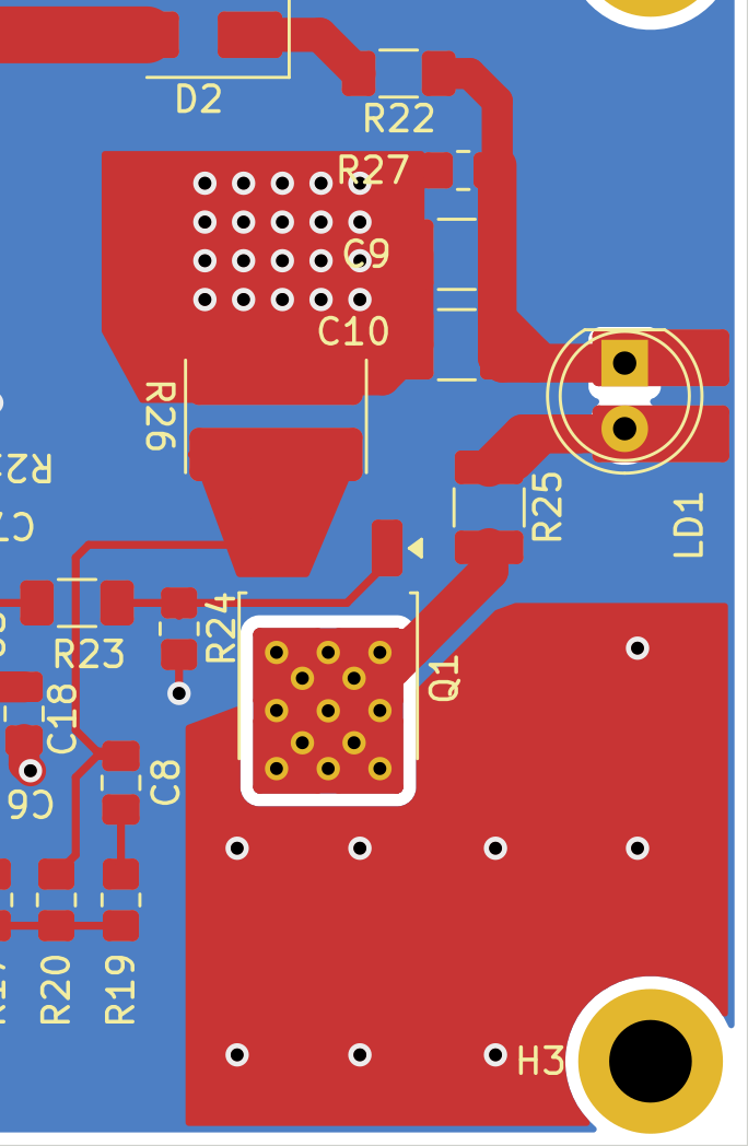
Fig. 2 show example of PCB heat management features. Q1 has a pad with thermal vias, it is not connected to GND because it is a different net. The via connection to the back of the board gives more dissipation area by itself and if that is not sufficient a heatsink can be fitted with conduction contact to the pad on the back. The top copper area is connected to GND. It helps to dissipate heat from the general region of the board even if it does not have electrical connection to Q1. FR4 has a thermal conductivity of is also placed near a mounting hole where a metal standoff and screw to a base give a heat conduction path to the baseplate.
Standard PCB copper thickness is 1 oz copper per 1 square foot which gives a thickness of 35µm or 1.4 mils. The thermal conductivity of copper is 401 W/(m⋅K) and for the FR4 material it is 0.25 W/(m⋅K). The copper has as dramatic 1600 times higher thermal conductivity. If we look at a slab of standard FR4 PCB with 1 oz copper and 1.57mm FR4 dielectric then the thermal resistance of the FR4 is only 35 times higher than that of the copper layer. That is because the FR4 is much thicker.
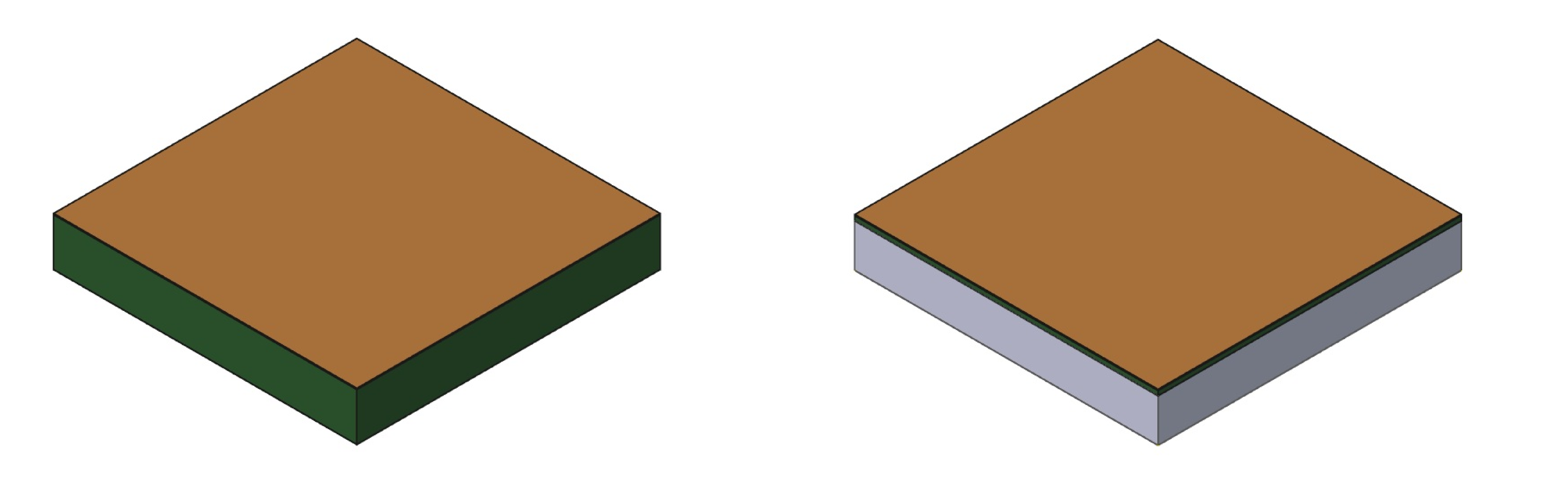
The thickness of the dielectric is set mainly for mechanical strength and rigidity. There are PCB designs that replace some dielectric thickness with metal. The most common is Aluminum backed PCB. It is sometimes called aluminum-based PCB or aluminum core PCB. Aluminum is an electrical conductor, so a layer of dielectric is still needed. Typically, 150 µm FR4 is used between copper layers and the aluminum backing. The metal backing has low thermal resistance and works well for spreading heat from hot spots.
Ultimately the heat has to be removed from the PCB. That is where a heatsink and fans can help.
Heatsinks
We call a heat conducting piece with dissipation fins for a heatsink. I am fine with that, as long as you think about where the heat eventually goes, into the atmosphere. The most common is black anodized extruded aluminum. Those with large fin separation are made for passive air flow. Hot air goes up, so orientation matter. Denser fins are found on heat sinks made for forced air flow, using a fan. The THERMAL RESISTANCE is given in °C/W or °K/W which is the same since it is the temperature difference between the heatsink surface and the air flow that matters. In the formula Q̇ = h *A *(T_s-T_f) , the datasheet value correspond to 1/(h *A) in °C/W. The better the heatsink is at dissipating heat the lower temperature increase per Watt heating. The value is given for different air flow speeds, the higher the speed the smaller temperature difference is needed per W dissipated.
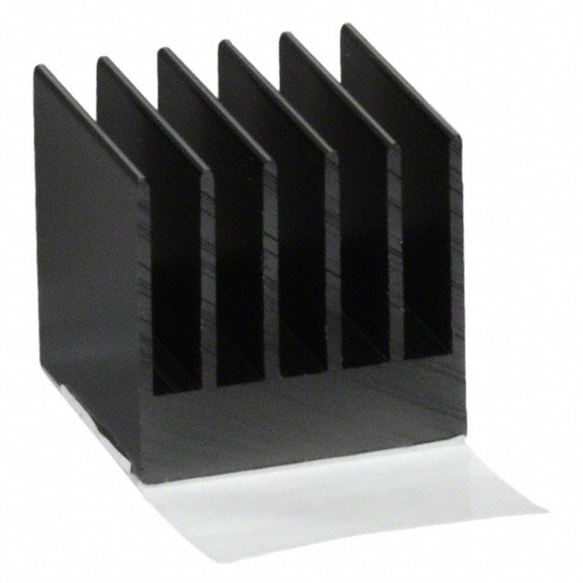
Fig. 4 is a picture of a small heatsink for local component cooling on a PCB. The geometry could just as well be for a 10 times larger heatsink for mounting on a baseplate for general device cooling. The fins increase the area for convection and thereby reduce the temperature difference at which a given heat is dissipated, see eq. 8. The fins are anchored in a thick base which spreads the heat by conduction from any hotspot so the heatsink gets a uniform temperature and all the fin area is utilized. The specification for this heatsink is 13.7 °C/W at 2 m/s airflow. If we calculate for the bare 15mm x 15mm PCB contact area we get 89 °C/W. The added surface area of a dissipator makes a large difference.
Heat pipes
Heat pipes are closed tube systems with a coolant that evaporate at the hot end and condensate at the cold end, thereby moving heat energy from the hot device to be cooled, to the cold side where the heat is dissipated to a heatsink. This is useful if the geometrical constraint of the system does not allow a heatsink to get in contact with the hot device directly.
Liquid cooling
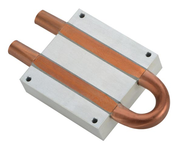
If large amounts of heat needs to be removed from a process then you will probably turn to liquid cooling. The liquid flowing in a tub system is brought in thermal conducting contact with the surface to be cooled. The picture shows a standard form factor liquid cooled heat sink. A copper tube is pressed and bonded into a cut in the block to give thermal contact. Water is the most common cooling liquid, but oil is also used.
Fans
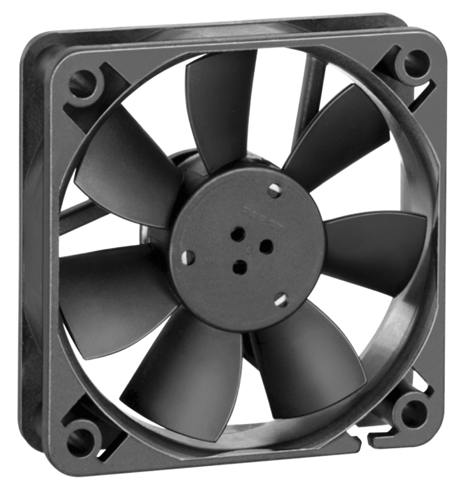
According to the dictionary a fan is an instrument used for producing artificial currents of air, by the wafting or revolving motion of a broad surface [Websters]. That is exactly the forced air flow that can help with cooling. Fans come in many sizes and shapes and with different DC and AC supply voltages. They are powered, so they do need some supply and control. That should be taken into consideration. Fan motors are potential sources of electrical noise and the power supply has to be separated from the circuitry of the system to cool. They have mechanical moving parts, which give noise and reliability issues. Fans are very useful because a smaller heatsink with forced airflow can dissipate the same as a much larger one without the fan. A duct that channel the airflow across the heatsink fins is increases efficiency. A thicker axial fan can give more pressure than a thin one, and therefore more air speed in a duct. Fig. 5 show a common fan, a 60mm x 60mm x 15mm axial fan. It is relatively thin so we do not expect that it can produce high pressure. It is typical used for general cabinet cooling. Maximum pressure at 0 m/s is 30 Pa, a thicker e.g. 32mm may give 10 times higher pressure. For forcing a high flow through a heatsink with dense fins require high pressure.
It does take some design effort to add a fan to the system, and they add to the overall power consumption. The cost and size of a heatsink is significant so in many cases adding a fan with its control does pay.
Interface materials
The interface material brings it all together to form a path for the heat from the where it is generated to the infinite mass heatsink.
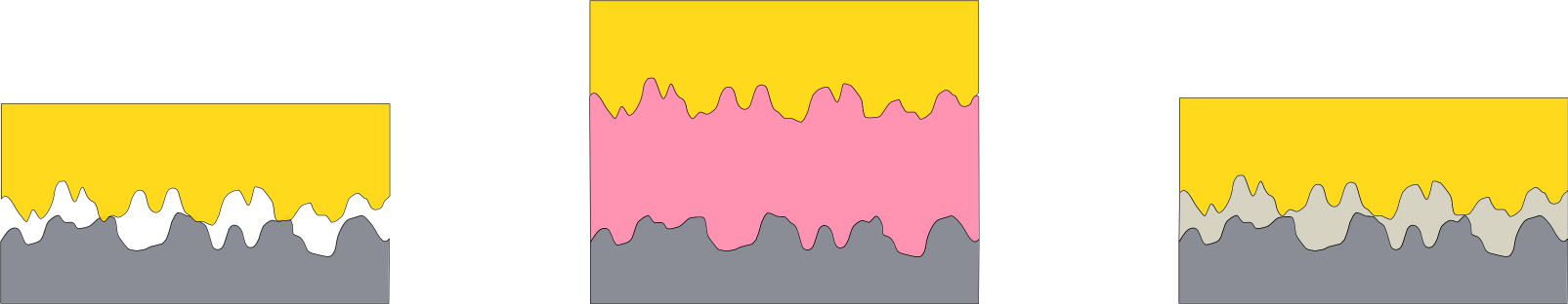
If you mate two supposedly flat surfaces then they will most likely only touch at three points.
For the heat conduction rate we have eq. 5 showing proportionality with the area. It is important to have a large contact area. To bridge the air gap we use a heat sink compound, paste or gel, or gap pad, see figure 4. There are two situations, either the heat sink can be at the same electrical potential as the heat sink or it has to be electrically isolated. In the first case a thin layer of heat sink paste works well. They are made from some grease with metal oxide powder added, often titanium oxide. Using a thermal paste insures that the separation (L) is as small as possible and that all gaps are filled.
Below is a table with thermal conductivity for some relevant material. Air has a low k-value of 0.025 W/(m·K), any material you can fill an air gap with will conduct about 10 times better. Some pastes or compounds are silicone oil based, they work fine, but the oil tends to migrate and can make soldering difficult and can cause screws to come loose. People talk about thermal compound drying and loosing its conductivity. My guess is that it comes from breaching a too large gap with the compound.
Make sure surfaces mate well, for example by flattening with a single cut file and fit with a small amount of heat sink compound.
If electrical isolation is need, then do the same but use a thin gap pad between parts.
Final words
We have seen that heat is generated in any powered system. Heats leads to temperature increase. Luckily the temperature gradient will drive the heat towards the cooler surroundings. Heat conduction, convection, and radiation are the main transport mechanisms. Heat management is the design effort that makes sure that the heat is removed at a tolerable temperature of the system.
Thermal Conductivity of selected materials
| Electrical conductor | k (W/(m·K)) |
|---|---|
| Copper | 401 |
| Aluminium | 237 |
| Indium | 86 |
| Gold | 320 |
| Graphite | 800 |
| Stainless Steel | 20 |
| Steel | 66 |
| Electrical isolator | k (W/(m·K)) |
| Diamond | 1000 |
| FR4 | 0.25 |
| Mica | 0.7 |
| Aluminium nitride (AlN) | 321 |
| Nylon 6 | 0.25 |
| SIL pad gap pad 0.15mm | 0.9 |
| GAP PAD 1000VOUS soft 1.5mm | 1 |
| Air | 0.025 |
| Silicone-Free Heat Sink Compound | 0.92 |
| Silicone sealant clear | 0.2 |
| Silicone rubber filled | 0.5 |
| Thermal Gel LF3800LVO | 3.8 |